
Abstract
While higher battery capacity increases a device’s operating life, keeping charging time down presents additional challenges for designers. Fast charging applies to a wide range of devices, including consumer, medical, and industrial applications. This two-part series provides an overview of the challenges associated with implementing battery fast charging capabilities. Part 1 discusses partitioning of the charger and fuel gauge between the host and battery pack to increase system flexibility, minimize power dissipation, and improve the overall user experience. It also covers monitoring functions that ensure safe charging and discharging. Part 2 will explore the implementation of a fast charging system with parallel batteries.
Introduction
In this era of mobile devices, battery life is one of the primary factors that affects the user experience. While implementing power saving technology inside devices is important, it is only one part of the solution. Given the increasing capabilities—and greater power requirements—of mobile devices, original equipment manufacturers (OEMs) also improve battery life by substantially increasing battery capacity.
For example, architectures like 1S2P (1 cell in series with 2 cells in parallel) that use two cells in parallel to increase overall capacity have become more popular. The downside of higher battery capacity is a corresponding increase in charging time. To minimize charging time, improvements in battery technology increase charge current from 2C up to 3C or 6C (that is, xC is x times the current that would pass through the rated ampere-hours of a battery in an hour). For example, a 2000 mAh cell could utilize up to 12 A of charging current without negatively affecting battery reliability.
High current requires special care to ensure safe charging and discharging. When using cells in parallel, developers also need to take care of impedance and initial capacity mismatches. In Part 1 of this article series, we’ll provide an overview of the challenges associated with implementing battery fast charging capabilities for devices of all types, including consumer, medical, and industrial applications.
We’ll also explore how to charge batteries in a 1S2P arrangement with high performance, as well as how to partition the charger and fuel gauge between the host and battery pack to increase system flexibility, minimize power dissipation, and improve the overall user experience.
Charger Basics and Why Fuel Gauge Partitioning Matters
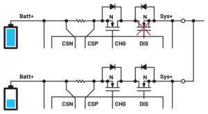
The key components of a battery charging system are the charger itself and the fuel gauge that reports metrics such as the battery state of charge (SOC), time to empty, and time to full. The fuel gauge can be implemented either on the host side or in the battery pack (see Figure 1).
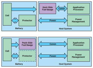
When implemented in the battery pack, the fuel gauge requires nonvolatile memory to store battery information. MOSFETs on the power path monitor charging/discharging currents and protect against dangerous conditions. A device like the MAX17330 from Analog Devices is a battery fuel gauge with built-in protection circuitry and battery charger capabilities (see Figure 2).
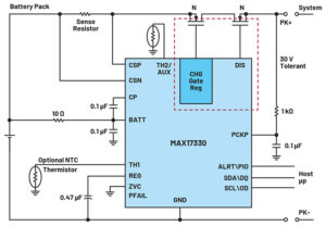
The charging MOSFET can be regulated with fine granularity to implement a linear charger that can be used as a standalone device when the charging source is limited to 5 V and the charge current is in the range of 500 mA. Since lithium battery charging exceeds 3.6 V for 99% of the charge curve, power dissipation is limited.
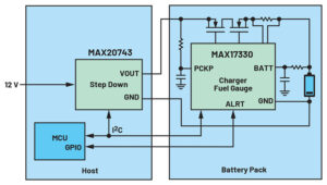
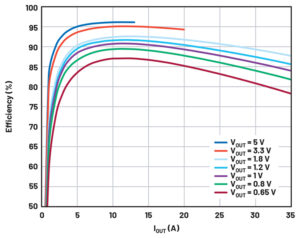
A high voltage charging source and high charging current can be accommodated using a step-down converter in front of the charger to regulate its output voltage (see Figure 3). This also minimizes dropout and therefore reduces power dissipation on the charging MOSFET (see Figure 4).
Implementing a fuel gauge in the battery pack enables the battery to become smart, enabling advanced charging scenarios and capabilities. For example, the fuel gauge can store the charging profile suitable for the cell inside the battery pack in its nonvolatile memory. This has the added benefit of offloading charging from the host microcontroller unit (MCU). Now the host MCU only needs to manage the ALRT signal coming from the battery pack to increase/decrease the output voltage of the step-down converter according to the alert type received.
CP: heat limit → decrease the voltage.
CT: MOSFET temperature limit → decrease the voltage.
Dropout: → increase the voltage
CP is a flag that is set when the current flowing in the protection MOSFETs can compromise thermal dissipation. CT is a flag that is set when the MOSFET temperature is too high. Heat limit and MOSFET limit settings are configured using the nChgCfg1 register set.
A programmable step-down converter like the MAX20743 uses the PMBus® to allow fine regulation of the output current. Integrated MOSFETs in the step-down converter support charging currents up to 10 A. In addition, since the PMBus uses I2C as its physical layer, a single I2C bus can be used to manage both the step-down converter and fuel gauge.
The following example shows a way to charge a single 3.6 V lithium cell. Figure 5 shows the time domain shape of the voltages and the currents in the charging system. Specifically, the graph shows the battery voltage, battery current, and output voltage of the buck converter.
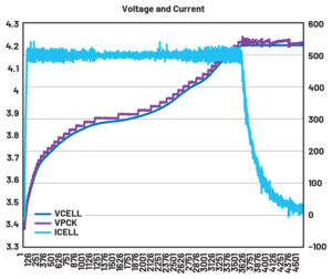
As can be seen, the step-down converter output (VPCK) is set to 50 mV above the battery voltage. This output voltage is constantly increased to avoid dropout as well as to minimize overall power dissipation.
Battery Safety Management
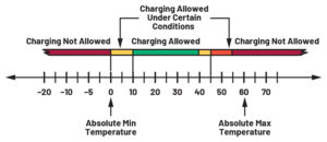
With the high currents involved in fast charging, OEMs must be able to guarantee safe charging. Thus, a smart fast charger must monitor several important parameters as part of its overall battery management. For example, by monitoring battery temperature and ambient/room temperature, a fast charger can determine when to reduce the charging current and/or lower the termination voltage to assure safety and improve the lifespan of the battery, according to cell manufacturer specifications and recommendations.
The voltage and current can be adjusted over temperature to comply with the six-zone JEITA temperature settings (see Figure 6) and with three-zone step-charging based on the battery voltage.
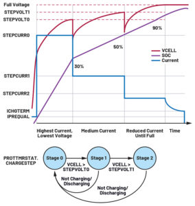
Battery lifespan can be further improved using a step-charging profile that changes charge current according to battery voltage. Figure 7 shows a step-charging profile that uses three charge voltages and three corresponding charge currents. Transitioning between the stages can be managed through a state machine (also see Figure 7).
Note that current, voltage, and temperature are all interrelated (see Table 1 and Table 2).
Parallel Charging
Parallel charging of multiple cells requires additional management. For example, the charger must prevent cross charging when the two batteries’ voltages differ by more than 400 mV. Cross charging can be tolerated for a limited time only when the lowest cell charge is too low to support system loading (see Table 3 and Figure 8).
Table 1. Charging Current with Step Charging and JEITA
| Temperature | Too Cold | Cold | Room | Warm | Hot | Too Hot |
| <0°C | 0°C to 10°C | 10°C to 40°C | 40°C to 45°C | 45°C to 55°C | >55°C | |
| Step 2 | No Charging | 0.19°C | 0.25°C | 0.22°C | 0.15°C | No Charging |
| Step 1 | No Charging | 0.38°C | 0.5°C | 0.44°C | 0.31°C | No Charging |
| Step 0 | No Charging | 0.75°C | 1°C | 0.88°C | 0.625°C | No Charging |
Table 2. Charging Voltage with Step Charging and JEITA
| Temperature | Too Cold | Cold | Room | Warm | Hot | Too Hot |
| <0°C | 0°C to 10°C | 10°C to 40°C | 40°C to 45°C | 45°C to 55°C | >55°C | |
| Step 2 | No Charging | 4.14 V | 4.2 V | 4.18 V | 4.16 V | No Charging |
| Step 1 | No Charging | 4.1 V | 4.16 V | 4.14 V | 4.12 V | No Charging |
| Step 0 | No Charging | 4.06 V | 4.12 V | 4.1 V | 4.08 V | No Charging |
Table 3. Management of FET Logic
| PAREN | BLOCKDIS | ALLOWCHGB | CHG FET | DIS FET |
| 0 | × | × | Normal | Normal |
| 1 | 0 | 0 | Normal | Normal |
| 1 | 0 | 1 (timeout) | Block Ready | Normal |
| 1 | 1 | 0 | Normal | Block Ready |
| 1 | 1 | 1 (timeout) | Block Ready | Normal |
In Part 2 of this article series, we’ll explore the implementation of a fast charging system with parallel batteries using evaluation kits and a Raspberry Pi board.
Conclusion
Moving charging and fuel gauge functionality from the host side to the battery pack allows individual control of each battery in a 1S2P configuration. Rather than requiring the host MCU to fully manage charging, a smart charger itself can manage its own output according to an optimal charging profile. Because management on the host side is limited to managing ALRT signals generated by the fuel gauge, systems can easily adapt to different battery packs.
A smart charger can also block charging and discharging when needed to prevent cross charging. This approach increases the flexibility of a typical fast charging system where battery mismatches are not considered. In addition to simplifying design and the overall charging process, OEMs can minimize power dissipation and ensure safe charging and discharging across a wide range of applications, all while improving the user experience with faster battery charging.
About the Authors
Franco Contadini has over 35 years of experience in the electronics industry. After 10 years as a board and ASIC designer, he became a field applications engineer supporting industrial, telecom, and medical customers and focusing on power and battery management, signal chains, crypto-graphic systems, and microcontrollers. Franco has authored several application notes and articles on signal chains and power. He studied electronics at ITIS of Genoa, Italy.
Alessandro Leonardi is an account manager at Analog Devices, Milan. He studied electronics engineering and received a bachelor’s and master’s degree from Politecnico di Milano. After graduating, he became part of the field applications trainee program at ADI.